# Entity Relationship Diagram Structure
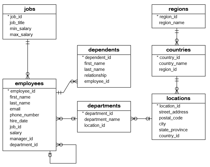
Entity Relationship Diagrams come in various formats, but they share common elements that help us understand the architecture of a database. As we progress through this course, we will explore different ways to represent ERDs. For now, let’s focus on a simple example using an HR database.
# HR Entity Relationship Diagram

Source: https://www.sqltutorial.org/sql-sample-database/
The data here should look familiar, it’s the diagram we used for the HR database in the Querying and Analysis assignment.
# Table Structure
The following properties are universal for all ERDs:
- Tables as Boxes: Each table in the database is represented as a box.
- Rows and Columns: Inside each box, the rows represent the columns of the table. When diagraming, we don’t care about what specific rows of data (e.g. the actual information for each employees). Instead we care about the structure of the tables themselves and how they relate to each other.
- Primary Key Notation: In this ERD, the primary key for each table is indicated with an asterisk (
*). Not every diagram uses an*, but they will always denote the primary key in some way.
Take the countries table for example. It is represented as a box in the HR Entity Relationship Diagram.
- Columns: Inside the box, you will find
country_id,country_name, andregion_id. While they are represented as rows in the diagram, these are actually the columns of the table in the database. - Primary Key: The
country_idis the primary key, as denoted by the*before it.
# Practice Questions
- According to the HR Entity Relationship Diagram, what will the columns be for the
countriestable? - Which column is the primary key for the
countriestable? How is the primary key shown in this diagram?